Skip to content
Search for:
Standards for Insulating links
ANSI/CPLSO-14
ANSI/UL2737 (Withdrawn)
ASTM F2973
MIL-L-24410 (Withdrawn)
Tests by Independent Organizations
Load Insulator
Miller & Hirtzer
Search for:
Download
Download Page
Download Right Page
1
2-3
4-5
6-7
8
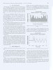
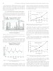
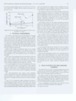
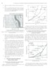
IEEE Transactions on Dielectrics and Electrical Insulation VoL 15, No. 2; April 2008 Figure 13 shows the peak value of the short duration tran- sient leakage current vs. test voltage for polluted and wet links. A line was drawn in Figure13 at 60 mA and at 300 mA. The intersections of these lines with the leakage current- voltage curves determine line-to-neutral voltage values, which marks the limits of the links that provide protection. Table 2. Summary of the protection limits provided by the links. Table 2 provides the summary of the protection limits for the links. In each case two criteria were used, a) the rms leak- age current and b) transient peak current. The criterion, which gives lower voltage value, is used as the final protection limit. The table clearly indicates that expected performance of Link B is better than Link A because Link B has significantly longer creepage distance than Link A. The protection limits depend on the severity of pollution. In generaX.the protection limit at light pollution is twice than at heavy pollution. Table 3 gives the maximum average stress and the corre- sponding allowable specific creepage distances for both links. These data can be used to estimate the performance of insulat- ing links with different creepage distances but similar shape. Insulating Link A is sold with several different lengths. As an example a shorter version of Link A with creepage distance of 240 mm provides adequate protection up to 240 mm x 37.9 Vlrnrn = 9096 V when heavily polluted. 6.4 PRACTICAL APPLICATIONS OF PROTECTION LIMITS The previous chapter gives the experimentally obtained maximum line-to-ground voltages, which are used to assess the level of protection provided by tested links. These voltages were converted to line-to-line voltages in Table 4. The crane worker is protected if the crane touches a line, and line-to-line voltage is less than the voltages listed in Table 4. Both polluted insulating links in dry condition provide per- fect protection (no harmful effect) up to the rated voltage of the link, which is 50 kV for link A and 25 kV for link B. The corresponding line-to-line voltage for Link A is 86.6 kV and Link B is 43.3 kV. The pollution and simultaneous wetting by fog reduces the level of protection below the rated voltage. This emphasizes the importance of regular maintenance. In order to ensure safety of personnel working on cranes with insulating links near overhead lines, it is essential to clean the insulating link prior to start of work. Table 4 shows that the light polluted and wetted Link A provides protection up to the lower sub-transmission voltage 6.3 PROTECTION PROVIDED BY LINKS USING ievel. (69 kV), which is below its rated voltage. Link B AVERAGE ELECTRICAL STRESS vide protection up to its rated voltage. The obtained results can be generalized by calculating and plotting the leakage current vs. average electrical stress Table 4. Summary of tested links provided protection. (Vlmm or Vlcm). The average electrical stress is calculated by dividing the test voltage by the creepage distance of the links. The creepage distance of Link A is 50.8 cm and Link B is 102 cm. Table 3. Maximum acceptable electrical field and specific creepage distances Perfect Protection (Harmless) I LinkA Link B I I I I LinkB IHeavy I 46.9 259.0 230.0 ILight I not tested I not tested The link providing protection is a probability phenomenon. The pollution and simultaneous wetting reduces the protection Pollution Heavy Light I I Adequate Protection (No fatal effect) LinkA IHeavy I 264.2 ILiaht
78 7 352.8 < 40.8 19.2 >Ail 0 Average electrical stem V/mm 23.4 47.2 Protection limit kV 11.9 24.0 28.3 224.5 14.4 >25.0
Page load link
Go to Top