Skip to content
Search for:
Standards for Insulating links
ANSI/CPLSO-14
ANSI/UL2737 (Withdrawn)
ASTM F2973
MIL-L-24410 (Withdrawn)
Tests by Independent Organizations
Load Insulator
Miller & Hirtzer
Search for:
Download
Download Page
Download Right Page
1
2-3
4-5
6-7
8
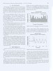
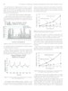
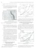
G. G. Karady et aL: Performance Evaluation of Insulating Links Used for Worker Protection in Cranes Fig a) There is no reaction, when the current is less than 0.5 mA. b) There is no harmful effect if the current is less than 10 mA. Based on these findings it can be concluded that a link provides perfect protection if the measured nns current was less than 10 mA. I Ventricular fibrillation cardiac and breathing arresl I Body current mP Temporally cardiac arrest breathing problems muscle reactior lure 11. Effect of current on human beings and livestock [14] (Marked up copy from IEC 60479-1). c) T&ere is no fatal effect if the current is less than 30 mA. However temporary health problems may occur. It can be concluded that the link provides adeauate protection if the measured rms current was less than 30 mA. d) At 60 mA no hard effect occurs usually if the du- ration is less than 100 milliseconds or around 6 cy- cles. But 60 mA is fatal if the duration is more than 1s. Due to the attenuation, the duration of the meas- ured transient peak current was less than 100 ms. Based on this findings it can be concluded that the link provides perfect protection if the short duration, transient peak current is less than 60 mA e) The effect is not fatal if the current is less than 300 mA and the duration is less than 100 rns; but 300 mA is fatal if the duration is more than 300 milliseconds. Based on the findings it can be concluded that a link provides adequate protection if the measured, short duration transient peak current is less than 300 mA. f) Above 500 mA the current will most likely cause a fatal accident. 6 PROTECTION PROVIDED BY INSULATING LINKS 6.1 PROTECTION PROVIDED BY LINKS BASED ON RMS LEAKAGE CURRENT Figure 12 shows the rrns value of the leakage current vs. test voltage of polluted and wet insulating links. Link A; E5iDO=O.133 Test Vo(tage (kV) Figure 12. Protection provided by Insulating link A and B using rms. cur- rent. In Figure 12 a line at 30 mA and at 10 mA have been drawn. The intersections of these lines with the leakage current- voltage curves determine line-to-neutral voltage values, which marks the limits of the links that provide protection. 6.2 PROTECTION PROVIDED BY LINKS BASED ON SHORT DURATION, TRANSIENT PEAK LEAKAGE CURRENT The sudden energization produced a short duration transient peak current. The duration of the current was between 0.5 to 5 cycles. Figure 11 shows that, in case of an accident, when the crane-transmission line contact drives current through the crane worker, 60 mA is harmless and 300 mA causes only temporary problems, but no fatal effect if the duration is less than 100 ms. do0 I I 1 Figure 13. Protection provided by Insulating link A and B using short dura- tion transient peak current. The short duration transient leakage current of the polluted and dry Insulating Link A, was 2.66 mA at 40 kV, this value corresponds to perfect protection (no harmful effect).
Page load link
Go to Top