Skip to content
Search for:
Standards for Insulating links
ANSI/CPLSO-14
ANSI/UL2737 (Withdrawn)
ASTM F2973
MIL-L-24410 (Withdrawn)
Tests by Independent Organizations
Load Insulator
Miller & Hirtzer
Search for:
Download
Download Page
Download Right Page
1
2-3
4-5
6-7
8
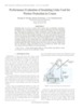
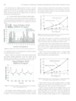
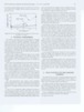
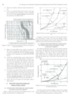
ZEEE Transactions on Dielectrics and Electrical Insulation VoL 15, No. 2; April 2008 457 the maximum peak leakage current of Link B was 14.38 mA at the rated 25 kV voltage. The rms current at the same volt- age was 4.1 rnA. -" 1 Peak current 150 RMS current 100 50 _----- 4t - - "20 22.5 25 27.5 30 ~est Voltage (kV) Figure 10. Peak and rms leakage current of Insulating Link B Heavy pollu- tion ESDD = 0.15 mg/cm2. 4 PHYSICAL PHENOMENA The flashover mechanism and the development of leakage current on suddenly energized insulating links are signifi- cantly different from what was observed on continuously en- ergized transmission line insulators. In both cases, the pollu- tion builds up slowly and fog or light rain wets the sample. In a continuously energized transmission line insulator the wet- ting produces a conducting layer and initiates leakage current, which~oduces dry bands. The dry bands initiate arcing that lasts for a relatively long period. Finally if the voltage is sufficiently high, the arc extends and the insulator would flashover. The leakage current varies slowly with the wetting and drying process. The leakage cur- rent amplitude is not very important because the insulator is grounded. In the case of an insulating link also the pollution builds up slowly and is wetted by fog or light rain. The wetting pro- duces a thin conductive layer on the polluted link. When the crane touches a transmission line, the line to ground voltage drives a transient leakage current though the wet layer. The current depends on the time of energization. The resis- tance of the polluted Link A varied between 1-6 MR depend- ing on the pollution level. Consequently, the test circuit is not inductive, which leads to the conclusion that the maximum leakage current occurs when the link is energized at the peak voltage. The crane-transmission line contact occurs randomly; which is simulated by the random energization of the link dur- ing the laboratory test. Figures 4 and 6 showed the statistical distribution of leakage currents produced by random energiza- tion. In the 10-1 5 kV range the sudden energization produces a fast attenuating transient current in both links. The transient current attenuates within 2-6 cycles to a significantly reduced more or less constant leakage current. The large transient leak- tance and attenuates the leakage current. In addition, the sud- den energization drives capacitive current through the link, which further increases the initial peak current. The resistance of the link was measured before and after the sudden energization using low ac voltages. The results show that the energization increases the link resistance. This finding lead to modification of the test procedure. The waiting time between consecutive energization was increased to several minutes, which allowed the fog to re-wet the link and reduce the resistance to the initial value. In the range of 20-35 kV the sudden energization produces partial arcs, which bridges a part of the link. Typically, the arc starts in the fust half cycle and lasts 3-6 cycles as shown in Figure 7. In the 35-40 kV range, occasional flashover was observed at heavy pollution, which occurred more frequently in the first half cycle. Sudden energization generates an arc that travels on the surface of the wet layer and bridges the link. This always produces unacceptable high leakage current. The visibility in the fog chamber was very low and it was difljcult to observe the arc development. In order to study the arcing phenomena, Insulating Link B was polluted by spray- ing. When it was completely wet the high voltage was switch- ed on. The current and voltage oscillograms proved that the arc frequently starts in the first cycle and attenuates within 2-5 cycles. The arcing always increased the peak value of the tran- sient leakage current. It was observed that the arc traveled on the wet surface. When the voltage was sufficiently large the arc bridged the insulator and produced flashover few times during the 25- energization attempts. Based on the experimental results it was concluded that the contact of the crane transmission line causes peak transient current with an estimated duration of less than 6 cycles. This is followed by more or less constant leakage current, which is characterized by its rms value. The transmission line protec- tion interrupts the rms. current, within an estimated time of 0.5s-3s. 5 HEALTH EFFECT OF THE LEAKAGE CURRENT The health effect of current on human beings and livestock is given by the international standard IEC 479-1. Figure 11 shows the effects of ac on human beings. It can be seen that under 10 mA no harmful effects were observed. For higher currents, the figure indicates that both the ampli- tude and duration of the current influences the biological ef- fects. As an example 100 mA for 2 seconds usually produces cardiac arrest and death. The same 100 mA current for dura- tion of 20 milliseconds has usually no harmful effect. In this investigation, zero resistance was assumed for skin and body, and footwear resistance was neglected. The figure shows that
Page load link
Go to Top